Add to Cart
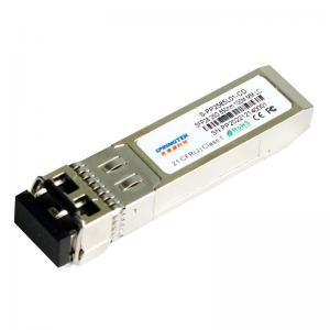
Brocade Compatible SFP28 SR 25G 100m Multi Mode Fiber LC MMF Transceiver
Ordering information
| Part Number | Product Description |
| S-PP2585L01-CD | SFP28, 25.78125Gbps, 850nm, SM, 100m, 0ºC~+70ºC, With DDM |
Description
Springtek SFP28 for 25Gigabit Ethernet and Infiniband EDR Applications. It is a high performance module for short-range data communication and interconnect applications which operate at 25.78125Gbps up to 70m using OM3 fiber or 100m using OM4 fiber. This module is designed to operate over multimode fiber systems using a nominal wavelength of 850nm.The electrical interface uses a 20 contact edge type connector. The optical interface uses duplex LC receptacle.
Features
Supports 25.78125Gbps bit rate
Maximum link length of 70m on OM3 MMF and 100m on OM4 MMF
850nm VCSEL laser and PIN photo detector
Internal CDR on both Transmitter and Receiver channe
Duplex LC receptacle
Operating environment temperature range: 0 ~ +70℃
Single 3.3V power supply
Low power dissipation: <1.0W
SFP28 housing with enhanced EMI shielding
Applications
25GBASE-SR Ethernet
Infiniband EDR Applications
32G Fibre Channel Applications
Servers, Switches, Storage and Host Card Adapters
Absolute Maximum Ratings
| Parameter | Symbol | Min | Typ | Max | Unit |
| Power Supply Voltage | Vcc | -0.5 | 3.6 | V | |
| Storage Temperature Range | Ts | -40 | 85 | °C | |
| Relative Humidity - Operating | RHO | 0 | 85 | % |
Recommended Operating Conditions
| Parameter | Symbol | Min | Typ | Max | Unit |
| Case Operating Temperature Range | Tc | 0 | - | 70 | °C |
| Power Supply Voltage | Vcc | 3.135 | 3.3 | 3.465 | V |
| Supply Current | Icc | - | - | 300 | mA |
| Data Rate | BR | 25.78125±100ppm | Gbps | ||
Electrical Characteristics
| Transmitter Electrical Characteristics | |||||
| Parameter | Symbol | Min | Typ | Max | Unit |
| Differential Input Voltage Swing | VIN | 90 | - | 100 | mV |
| Tx Differential Input Impendence | ZIN | - | 100 | - | Ω |
| Transmitter Disable Voltage | VDIS | 2.0 | - | VCC+0.3 | V |
| Transmitter Enable Voltage | VEN | 0 | - | 0.8 | V |
| Receiver Electrical Characteristics | |||||
| Parameter | Symbol | Min | Typ | Max | Unit |
| Differential output Voltage Swing | VOUT | 300 | - | 900 | mV |
| Rx Differential Output Impendence | ZOUT | - | 100 | - | Ω |
| LOS Assert Voltage | VLOSA | 2.0 | - | VCC+0.3 | V |
| LOS De-assert Voltage | VLOSD | -0.3 | - | +0.4 | V |
Optical Characteristics
| Parameter | Symbol | Min | Typ | Max | Unit | Notes | ||
| Transmitter Characteristics | ||||||||
| Center Wavelength Range | λ | 840 | 850 | 860 | nm | |||
| Spectral Width RMS | Δλ | - | - | 0.6 | nm | |||
| Average Output Power | Pavg | -8.4 | 2.4 | dBm | ||||
| Optical Power OMA | POMA | -6.4 | 3 | dBm | ||||
| Extinction Ratio | ER | 2 | - | - | dB | |||
| Relative Intensity Noise | RIN | - | - | -128 | dB/Hz | |||
| Optical Return Loss Tolerance | - | - | 12 | dB | ||||
| Transmitter and Dispersion Eye Closure | TDEC | - | - | 4.3 | dB | |||
| Transmitter Eye mask definition {X1,X2, X3, Y1, Y2, Y3} | >10% {0.23, 0.34, 0.43, 0.27, 0.35, 0.4} | 1,2 | ||||||
| Receiver Characteristics | ||||||||
| Operating Central Wavelength | λ | 840 | 850 | 860 | nm | |||
| Receiver Sensitivity | Sen | - | - | -10.3 | dBm | 3,4 | ||
| Receiver Overload | PSAT | 2.4 | - | - | dBm | |||
| Receiver Reflectance | RFL | - | - | -12 | dB | |||
| LOS Assert | LOSA | -30 | - | - | dBm | |||
| LOS De-Assert | LOSD | - | - | -13 | dBm | |||
| LOS Hysteresis | LOSH | 0.5 | 3 | 5 | dB | |||
| Notes | ||||||||
| 1. Transmitter hit ratio 5E-5 hits/sample. 2. Compliant with IEEE 802.3ba. 3. Minimum value is informative, equals min Tx OMA with infinite ER and max channel insertion loss. 4. Receiver Sensitivity measured with a PRBS 231-1 test pattern, @25.78125Gb/s, BER<5E-5. | ||||||||